Projects
Selected engineering, robotics, software, electronics and research projects spanning professional, academic and personal work.
Modelling, System Identification and Control of a Boiler Heating System
Working on contract for a UK based boiler manufacturer, I successfully decoupled a Multi-Input Multi-Output (MIMO) system into two Single-Input Single-Output (SISO) systems to allow for full automation in their R&D process.
Modelling, System Identification and Control of a Boiler Heating System
Working on contract for a UK based boiler manufacturer, I successfully decoupled a Multi-Input Multi-Output (MIMO) system into two Single-Input Single-Output (SISO) systems to allow for full automation in their R&D process.
TODO.
End of Line Calibration and Test System for Vacuum Mounts Used in Wafer Lithography
This Automated Test Equipment (ATE) calibrates and tests vacuum mounts used for mounting wafers during lithographic fabrication.
End of Line Calibration and Test System for Vacuum Mounts Used in Wafer Lithography
This Automated Test Equipment (ATE) calibrates and tests vacuum mounts used for mounting wafers during lithographic fabrication.
I inherited this project from a previous engineer who had left the company. The ATE was a complex mechatronic device comprising a vacumm/pneumatic system, a vision system, motor drives and a 3-axis gantry used to introduce a rotating tool to potentiometers on the Device Under Test (DUT), a PLC and a control PC and was designed to be run in a cleanroom. The point at which I inherited this project is when it was returned from the customer site for failing the Site Acceptance Test (SAT), having experienced a fire when testing the motor drives. There had not been a Factory Acceptance Test (FAT) performed on the system before it was shipped to the customer.
Each DUT required calibration, incorporating four vacuum/pressure ports, three potentiometers for voltage calibration across different pneumatic stages, and a serial connection for internal state feedback
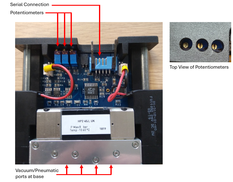
On taking ownership of the project, I identified significant deficiencies across virtually every system and subsystem, requiring a comprehensive technical overhaul. The subcontracted electrical build was incomplete, with no wiring diagrams or wire labelling, incorrect PLC connections, ground loops, and conductors of insufficient gauge for the required current. The PLC software and hardware integration were also incomplete. The control software lacked defined test sequences and failed to communicate reliably with much of the system I/O, while the test sequencing engine remained unfinished and untested. The vision system had been specified with an incorrect lens, preventing the GigE camera from focusing adequately on the potentiometers under test, and the camera was connected through an unsuitable 100 Mb/s network switch rather than the required 1 Gb/s infrastructure. The associated vision software was unfinished and untested. Mechanically, the specification demanded gantry positioning tolerances of approximately 10 µm without adequately accounting for tooling concentricity and other sources of mechanical error. The vacuum/pressure systems were untested and their control logic incomplete. In addition, communications between the PLC and external control PC contained a memory leak that compromised long-duration system stability. As a result, substantial redesign, completion, integration and validation were required across the electrical, mechanical, pneumatic, vision and software domains before the system could operate as a reliable automated test platform.
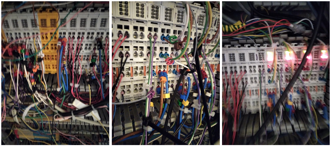
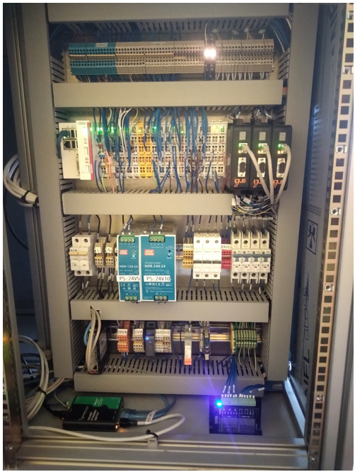
The ATE required an almost complete re-engineering effort, but without the benefit of the originally agreed timescales or project budget. A lot of the work was done in parallel, with project dependencies informing each other as the refactor developed. As such, whilst an attempt has been made to present this somewhat chronologically, it is not entirely accurate. One of the first key milestones was I/O mapping, rewiring the PLC connections and tidying up the connections. Note that a wiring diagram was produced and all wires were tagged.
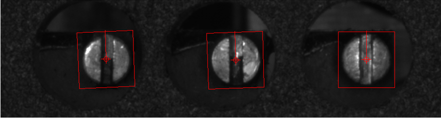
I eliminated the communication problems and memory leak between the PLC and the external control PC by rewriting the software interfaces, which was validated with robust multi-day testing whilst I worked on other subsystems. To enable the camera to focus on its target I designed a new camera mount (at a different height) and had it fabricated, which was both faster and cheaper than sourcing a new lens. I then developed the vision software. Image acquisition was written in C++, while a machine-learning vision module written in LabVIEW evaluated the location and orientation of each potentiometer in the ATE workspace, with the output being gantry x–y target coordinates and the required tool rotation angle.
Tool concentricity was also an issue, so I designed a new tool mount which used a guiding flange to guarantee reliable engagement with the potentiometers, using the principles of embodied intelligence. In retrospect, this would have enabled the use of a much cheaper gantry system with a less precise tolerance.
TODO. Motion videos.
Automatic LabVIEW Class and Inheritence Generator from Mermaid Diagrams
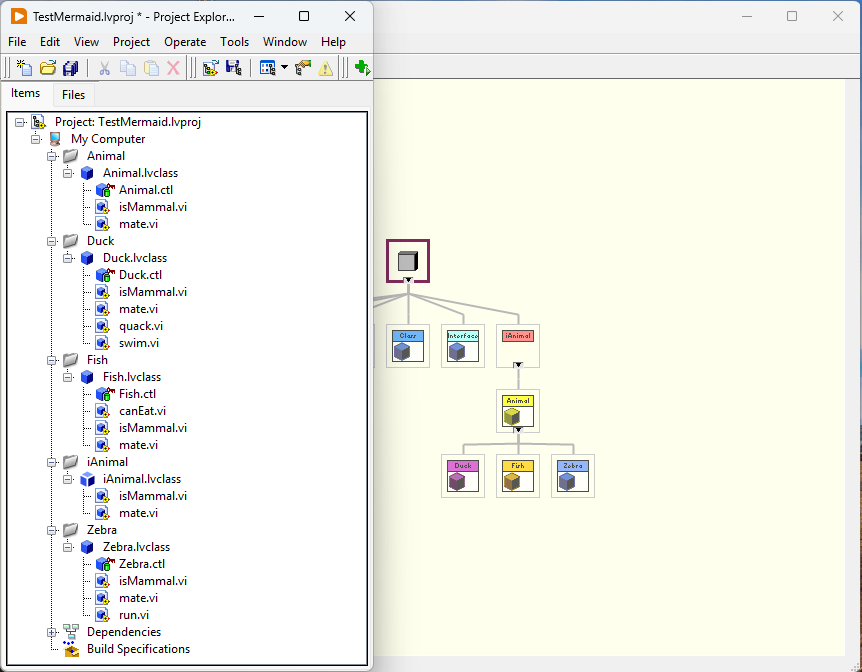
I have created an open source tool that automatically generates LabVIEW classes and establishes inheretence relationships between them based on Mermaid diagrams. This tool allows developers to visually design their class structures using Mermaid syntax, and then automatically generate the corresponding LabVIEW code, saving time and reducing errors in the development process.
The tool automatically converts Mermaid markdown defined class diagrams into LabVIEW class structures uisng VI scripting, preserving the full class heirarchy.
View UML source
                    ---
        title: Animal example
        ---
        classDiagram
            class iAnimal{
                +isMammal()
                +mate()
            }
            class Animal{
                +int age
                +String gender
                +isMammal()
                +mate()
            }
            class Duck{
                +String beakColor
                +swim()
                +quack()
            }
            class Fish{
                -int sizeInFeet
                -canEat()
            }
            class Zebra{
                +bool is_wild
                +run()
            }
            iAnimal <|-- Animal
            Animal <|-- Duck
            Animal <|-- Fish
            Animal <|-- Zebra
The source code and a deployable VI Package may be found in my Github:
Emergency software replacement for a Bed of Nails programming station used in the assembly-line production of telehealthcare devices.
The customer urgently required a complete software replacement for a production programming station operating at the end of an assembly line. The station relied on legacy software running on a Windows XP machine which had suffered a terminal hardware failure, immediately preventing further production. With no viable replacement for the original system, the software had to be rapidly recreated and migrated onto a modern Windows 10 platform so that manufacturing could resume.
This project was delivered under significantly different constraints to a typical engineering development. The programming station was production-critical, the customer had already fallen behind schedule, and the outage was costing hundreds of pounds per hour. As a result, the priority was rapid restoration of a reliable production capability rather than development of an extensively abstracted or reusable software architecture. I implemented a straightforward state-machine architecture that closely followed the physical manufacturing sequence, minimising unnecessary complexity while keeping the execution flow deterministic and easy to diagnose.
The programming station performed several tightly integrated manufacturing operations. Once the Unit Under Test (UUT) was placed into the fixture and the lid closed, an overhead Bed of Nails assembly was lowered onto electrical test and programming points on the PCB. A Cognex vision system then captured the barcode located on the underside of the product clamshell. The barcode data was parsed and used to query a network database, identifying the specific hardware configuration and the corresponding firmware required for that unit. The selected firmware was then flashed to the device using a SEGGER programmer. Following programming, the station performed a series of electrical and communications checks, including I2C transactions and basic voltage and current measurements, to confirm both correct PCB assembly and successful firmware deployment.
The programming and preliminary test sequence took approximately 45 seconds. These first-pass checks were intentionally performed at the programming station because the downstream Automated Test Equipment (ATE) required approximately three minutes to execute its complete test suite. Detecting common assembly or programming faults at this earlier stage therefore prevented defective units from occupying the main ATE unnecessarily and improved overall production-line throughput.
The emergency rewrite was complicated by the condition of the legacy system. A significant proportion of the original source code had been lost, with no complete backup available, and several hardware interfaces depended on obsolete drivers and software components originally designed for Windows XP. Considerable effort was therefore required to identify the interfaces being used, locate compatible drivers and SDKs, and reproduce the behaviour of the original application on Windows 10.
Despite these constraints, the replacement system was successfully developed and deployed into production within two days. In addition to restoring the original programming and test functionality, I simplified the operator workflow. The legacy application required the operator to interact with the user interface and interpret several intermediate results. In the replacement system, closing the fixture lid automatically initiated the complete programming and test sequence. The operator was presented with a clear Pass/Fail result when the cycle completed, with additional diagnostic information displayed only when a failure occurred. Operator feedback following deployment was very positive, and the simplified workflow reduced both interaction time and the opportunity for interpretation errors.
TODO. Images.
Realtime Control of Magnetically Actuated Soft Continuum Robots (MSCRs) using a hybrid Non-Linear Optimisation/Genetic Algorithm solver to Perform the Inverse Kinematics
Magnetically Actuated Soft Continuum Robots (MSCRs) are difficult to control since there is no closed-form solution for the inverse kinematics. This is because they essentially have infinite degrees of freedom. I solved the Inverse Kinematics in real time using a computationally efficient hybrid algorithm combining the benefits of non-linear optimisation with the benefits of a genetic algorithm.
MSCRs, developed by STORM lab at the University of Leeds, are soft robots that can be actuated using magnetic fields and field gradients. They are fabricated by vacuum mixing silicone with strong magnetic particles (NdFeB) and then curing the mixture in a 3D printed mould. The resulting soft robot is then directionally magnetised and can be actuated by applying magnetic fields and field gradients. The soft robots are used for a variety of applications, including minimally invasive surgery, drug delivery, and soft robotics research.
However, the MSCRs are challenging to control due to their complex dynamics and the lack of a closed-form inverse kinematics solution. Furthermore, in the context of endoluminal applications in minimily invasive surgery, positional feedback is challenging. The difficulty in locating the MSCRs using tradionall mechanisms such as Ultrasound make localisation and therefore automating the path planning and control of the MSCRs very difficult.
TODO. Images.
Impedance Controlled Automated Scanning of Complex Tissue Geometries
Impedance Control was used with a Kuka iiwa 14, with a 6-axis load cell and THz scanner at the end effector, to obtain THz scans of complex and delicate tissues. Force feedback was used to align the scanner such that all scans were normal to the tissue surface
TODO. This too was a very complicated project.
Initially, an impedance control scheme was planned. This was implemented and validated on a rigid 3D printed test sample. Note that the robot is probing towards the sample, and if the contact is not normal to the surface it retracts, repositions and then probes again the exact same location but this time normal to the surface. Contact forces were measured by a 6-axis ATI loadcell, with the load data presented to the ROS 2 network by a Beckhoff PLC.
TODO. Summary.
Ultra-precise Hexapod Scanning for Novel THz Sensor Validation.
Colleagues in the THz Research group had developed a novel THz sensor. The sensor surface was unprotected and incredibly delicate, making it very difficult to validate. I developed soft silicone samples and introduced them to the chip/sensor surface using an ultraprecise Hexapod.
The novel Thz sensor consisted of a single chip, but the surface was unprotected and incredibly delicate. Normally, to validate the response of the chip test samples of known THz response are introduced to the sensing area and the response measured and compared against the expected response. One of the most common samples used for this is Gallium Arsenide (GaAs), but unfortunately this is very toxic and also a very hard crystal, which would almost certainly destroy the surface of the sensor when introduced. I worked with my colleagues in the THz lab to introduce samples to validate the response of the sensor.
The first attempt used 3D printed samples (Form 3 - V3 Grey Resin), which had been characterised for their response attched to an ultra precise Hexapod (Solano, by Symmetrie). The samples were characterised for their THz properties by the THz group. The key requirement for the test procedure was to introduce the samples to within a range of 2-5 um of the sensing area, but not to achieve contact to protect the chip surface.
WRITE SOMETHING ABOUT SURFACE ASPERITIES, POLISHING, etc....
Despite all the work to fabricate a 3D printed sample, we were not successful in obtaining a response. Much of this is that we could never be sure how close to the senstive area we were able to get, and we did not want to make contact and almost certianly destroy the chip. As a result, we decided to instead characterise a silicone and use silicone samples, which were compliant enough that we had confidence to directly interface with the chip (hopefully non-destructively).
TODO. Summary, videos.
Kuka iiwa Platform Upgrade for ROS2 Compatibility.
A package of software was written and deployed to allow both the Dual Platform or an individual Kuka to be accessible on a ROS2 network. Previously, the Lab had been constrained to using ROS1 due to reliance on an open source ROS1Java library.
Kuka iiwa Platform Upgrade for ROS2 Compatibility.
A package of software was written and deployed to allow both the Dual Platform or an individual Kuka to be accessible on a ROS2 network. Previously, the Lab had been constrained to using ROS1 due to reliance on an open source ROS1Java library.
TODO.