Professional experience in robotics, systems engineering, software, control and multidisciplinary engineering.
Employment
Systems Engineer
Key Engineering Solutions Ltd
Dec 2025 – Present
Delivery of multidisciplinary engineering projects spanning software, automation, instrumentation, electronics and system integration.
Contract R&D across a range of projects, spanning medical device development, AI, machine vision, electronics and PCB design, simulation, hardware integration, testing and validation. Software architecture and development in C++, Python and LabVIEW, covering embedded systems through to networked applications and database integration.
Brought the company up from little source code control to a full Continous Integration and Continuous Deployment (CI/CD) pipeline for automated test and deployment of developed software.
Led the deployment of software security testing to meet the EU Cyber Resilience Act legislation.
Modelling and Control of complex coupled systems.
Selected Projects
Modelling, System Identification and Control of a Boiler Heating System
Working on contract for a UK based boiler manufacturer, I successfully decoupled a Multi-Input Multi-Output (MIMO) system into two Single-Input Single-Output (SISO) systems to allow for full automation in their R&D process.
Upgraded the dual-arm Kuka iiwa platform (Composed of 2 Kuka iiwa 14 robots in a shared robotic workspace) from ROS1 to a ROS2 interface, overcoming the unique challenges presented by Kuka’s closed ecosystem. The robots were fitted with large magnets at their end-effectors, creating a complex magnetic workspace which was used to manipulate Magnetically Actuated Soft Continuum Robots (MSCRs).
Developed path planning and control algorithms for the dual-arm Kuka platform, considering the field and gradient effects of the large magnets at the end effectors to precisely manipulate shape and position of MSCRs for minimally invasive surgery applications.
Led path planning and control efforts for a single-arm Kuka iiwa robot, integrating bespoke toolchains at the end effector, including an ultra-precise 6-DoF hexapod and a combination of 6-axis loadcell/THz sensing chip array for impedance controlled soft surface scanning.
Designed and fabricated doped silicone phantoms for characterisation and validation of THz scanning technology for use in a medical context. Samples ranged in scale from a forearm representative sample comprised of multiple layers of different materials and thicknesses representing all major tissue components to sub millimeter patterned samples used in ultra high resolution scanning.
Supervised MSc students through their Electronic Engineering professional projects, worth 50% of their grade.
Selected Projects
Realtime Control of Magnetically Actuated Soft Continuum Robots (MSCRs) using a hybrid Non-Linear Optimisation/Genetic Algorithm solver to Perform the Inverse Kinematics
Magnetically Actuated Soft Continuum Robots (MSCRs) are difficult to control since there is no closed-form solution for the inverse kinematics. This is because they essentially have infinite degrees of freedom. I solved the Inverse Kinematics in real time using a computationally efficient hybrid algorithm combining the benefits of non-linear optimisation with the benefits of a genetic algorithm.
+
MSCRs, developed by STORM lab at the University of Leeds, are soft robots that can be actuated using magnetic fields and field gradients. They are fabricated by vacuum mixing silicone with strong magnetic particles (NdFeB) and then curing the mixture in a 3D printed mould. The resulting soft robot is then directionally magnetised and can be actuated by applying magnetic fields and field gradients. The soft robots are used for a variety of applications, including minimally invasive surgery, drug delivery, and soft robotics research.
However, the MSCRs are challenging to control due to their complex dynamics and the lack of a closed-form inverse kinematics solution. Furthermore, in the context of endoluminal applications in minimily invasive surgery, positional feedback is challenging. The difficulty in locating the MSCRs using tradionall mechanisms such as Ultrasound make localisation and therefore automating the path planning and control of the MSCRs very difficult.
Impedance Controlled Automated Scanning of Complex Tissue Geometries
Impedance Control was used with a Kuka iiwa 14, with a 6-axis load cell and THz scanner at the end effector, to obtain THz scans of complex and delicate tissues. Force feedback was used to align the scanner such that all scans were normal to the tissue surface
+
TODO. This too was a very complicated project.
Initially, an impedance control scheme was planned. This was implemented and validated on a rigid 3D printed test sample. Note that the robot is probing towards the sample, and if the contact is not normal to the surface it retracts, repositions and then probes again the exact same location but this time normal to the surface. Contact forces were measured by a 6-axis ATI loadcell, with the load data presented to the ROS 2 network by a Beckhoff PLC.
Impedance controlled Kuka iiwa probing a curved 3D printed sample with sub-Newton contact forces.Impedance controlled Kuka iiwa probing the complex geometric anatomy of a heart with sub-Newton contact forces, and registering the surface and surface normals.The Kuka iiwa using the surface registration to perform a THz scan of the surface of the heart.
Ultra-precise Hexapod Scanning for Novel THz Sensor Validation.
Colleagues in the THz Research group had developed a novel THz sensor. The sensor surface was unprotected and incredibly delicate, making it very difficult to validate. I developed soft silicone samples and introduced them to the chip/sensor surface using an ultraprecise Hexapod.
+
The novel Thz sensor consisted of a single chip, but the surface was unprotected and incredibly delicate. Normally, to validate the response of the chip test samples of known THz response are introduced to the sensing area and the response measured and compared against the expected response. One of the most common samples used for this is Gallium Arsenide (GaAs), but unfortunately this is very toxic and also a very hard crystal, which would almost certainly destroy the surface of the sensor when introduced. I worked with my colleagues in the THz lab to introduce samples to validate the response of the sensor.
The first attempt used 3D printed samples (Form 3 - V3 Grey Resin), which had been characterised for their response attched to an ultra precise Hexapod (Solano, by Symmetrie). The samples were characterised for their THz properties by the THz group. The key requirement for the test procedure was to introduce the samples to within a range of 2-5 um of the sensing area, but not to achieve contact to protect the chip surface.
Left: Tip control. Right: Base Control.
WRITE SOMETHING ABOUT SURFACE ASPERITIES, POLISHING, etc....
Despite all the work to fabricate a 3D printed sample, we were not successful in obtaining a response. Much of this is that we could never be sure how close to the senstive area we were able to get, and we did not want to make contact and almost certianly destroy the chip. As a result, we decided to instead characterise a silicone and use silicone samples, which were compliant enough that we had confidence to directly interface with the chip (hopefully non-destructively).
Two silicone samples. The first is pure silicone, and the second was cast with some Gallium Arsenide at its tip. Note their compliance
Kuka iiwa Platform Upgrade for ROS2 Compatibility.
A package of software was written and deployed to allow both the Dual Platform or an individual Kuka to be accessible on a ROS2 network. Previously, the Lab had been constrained to using ROS1 due to reliance on an open source ROS1Java library.
+
TODO.
The Dual Arm platform manipulating a Magnetically Actuated Soft Continuum Robot, running through my new ROS2 interface
Designed, built, installed, programmed, and validated bespoke Automated Test Equipment (ATE) systems and process control platforms for customers in the nuclear, manufacturing, medical device, chemical and rail industries. Delivered projects end-to-end, from initial requirements gathering through to Factory Acceptance Test (FAT) and Site Acceptance Test (SAT)
Developed low-level drivers in LabVIEW and C++ to control and acquire from a variety of hardware. Examples include stepper motor drives, GigE cameras, fluid control assemblies, and pneumatic assemblies.
Developed code to communicate with a wide range of hardware using standard protocols (I2C, SPI, TCP, UDP, UART, Modbus, OPC) as well as bespoke serial across RS232.
Designed and implemented automated test frameworks including sequencing engines, operator interfaces, results logging, and PLC integration. Development was primarily in LabVIEW and C++, with Beckhoff PLC control implemented in TwinCAT 3 using Structured Text (ST)
Selected Projects
End of Line Calibration and Test System for Vacuum Mounts Used in Wafer Lithography
This Automated Test Equipment (ATE) calibrates and tests vacuum mounts used for mounting wafers during lithographic fabrication.
+
I inherited this project from a previous engineer who had left the company. The ATE was a complex mechatronic device comprising a vacumm/pneumatic system, a vision system, motor drives and a 3-axis gantry used to introduce a rotating tool to potentiometers on the Device Under Test (DUT), a PLC and a control PC and was designed to be run in a cleanroom. The point at which I inherited this project is when it was returned from the customer site for failing the Site Acceptance Test (SAT), having experienced a fire when testing the motor drives. There had not been a Factory Acceptance Test (FAT) performed on the system before it was shipped to the customer.
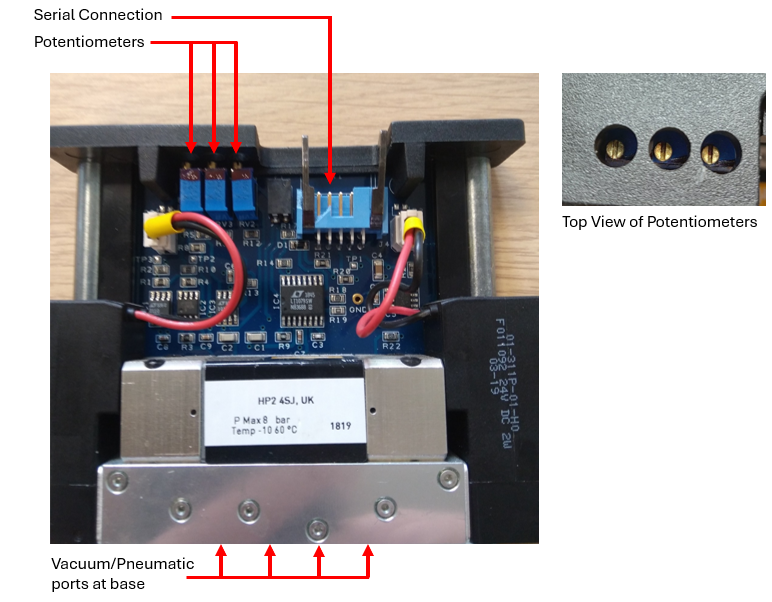
Each DUT required calibration, incorporating four vacuum/pressure ports, three potentiometers for voltage calibration across different pneumatic stages, and a serial connection for internal state feedback
The Device Under Test (DUT).
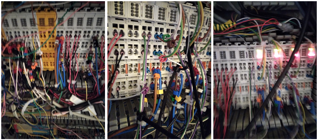
On taking ownership of the project, I identified significant deficiencies across virtually every system and subsystem, requiring a comprehensive technical overhaul. The subcontracted electrical build was incomplete, with no wiring diagrams or wire labelling, incorrect PLC connections, ground loops, and conductors of insufficient gauge for the required current. The PLC software and hardware integration were also incomplete. The control software lacked defined test sequences and failed to communicate reliably with much of the system I/O, while the test sequencing engine remained unfinished and untested. The vision system had been specified with an incorrect lens, preventing the GigE camera from focusing adequately on the potentiometers under test, and the camera was connected through an unsuitable 100 Mb/s network switch rather than the required 1 Gb/s infrastructure. The associated vision software was unfinished and untested. Mechanically, the specification demanded gantry positioning tolerances of approximately 10 µm without adequately accounting for tooling concentricity and other sources of mechanical error. The vacuum/pressure systems were untested and their control logic incomplete. In addition, communications between the PLC and external control PC contained a memory leak that compromised long-duration system stability. As a result, substantial redesign, completion, integration and validation were required across the electrical, mechanical, pneumatic, vision and software domains before the system could operate as a reliable automated test platform.
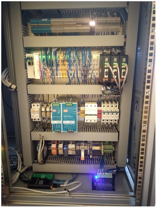
The ATE required an almost complete re-engineering effort, but without the benefit of the originally agreed timescales or project budget. A lot of the work was done in parallel, with project dependencies informing each other as the refactor developed. As such, whilst an attempt has been made to present this somewhat chronologically, it is not entirely accurate. One of the first key milestones was I/O mapping, rewiring the PLC connections and tidying up the connections. Note that a wiring diagram was produced and all wires were tagged.
PLC Cabinet Before Remapping and Rewiring.PLC Cabinet After Remapping and Rewiring.
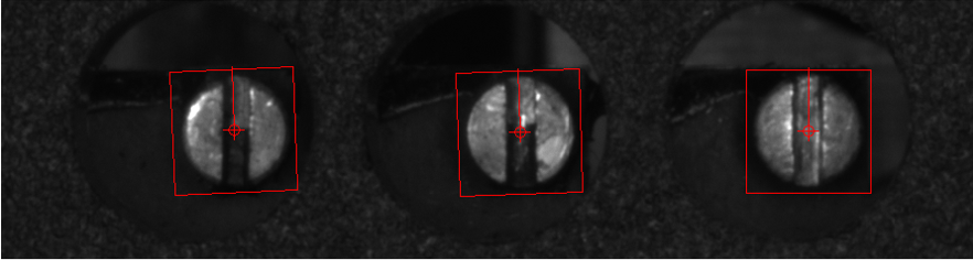
I eliminated the communication problems and memory leak between the PLC and the external control PC by rewriting the software interfaces, which was validated with robust multi-day testing whilst I worked on other subsystems. To enable the camera to focus on its target I designed a new camera mount (at a different height) and had it fabricated, which was both faster and cheaper than sourcing a new lens. I then developed the vision software. Image acquisition was written in C++, while a machine-learning vision module written in LabVIEW evaluated the location and orientation of each potentiometer in the ATE workspace, with the output being gantry x–y target coordinates and the required tool rotation angle.
Successful Potentiomter Identification.
Tool concentricity was also an issue, so I designed a new tool mount which used a guiding flange to guarantee reliable engagement with the potentiometers, using the principles of embodied intelligence. In retrospect, this would have enabled the use of a much cheaper gantry system with a less precise tolerance.
Beckhoff TwinCATStructured TextPLCC++PythonLabVIEWIDS GigE Camera
Emergency software replacement for a Bed of Nails programming station used in the assembly-line production of telehealthcare devices.
The customer urgently required a complete software replacement for a production programming station operating at the end of an assembly line. The station relied on legacy software running on a Windows XP machine which had suffered a terminal hardware failure, immediately preventing further production. With no viable replacement for the original system, the software had to be rapidly recreated and migrated onto a modern Windows 10 platform so that manufacturing could resume.
+
This project was delivered under significantly different constraints to a typical engineering development. The programming station was production-critical, the customer had already fallen behind schedule, and the outage was costing hundreds of pounds per hour. As a result, the priority was rapid restoration of a reliable production capability rather than development of an extensively abstracted or reusable software architecture. I implemented a straightforward state-machine architecture that closely followed the physical manufacturing sequence, minimising unnecessary complexity while keeping the execution flow deterministic and easy to diagnose.
The programming station performed several tightly integrated manufacturing operations. Once the Unit Under Test (UUT) was placed into the fixture and the lid closed, an overhead Bed of Nails assembly was lowered onto electrical test and programming points on the PCB. A Cognex vision system then captured the barcode located on the underside of the product clamshell. The barcode data was parsed and used to query a network database, identifying the specific hardware configuration and the corresponding firmware required for that unit. The selected firmware was then flashed to the device using a SEGGER programmer. Following programming, the station performed a series of electrical and communications checks, including I2C transactions and basic voltage and current measurements, to confirm both correct PCB assembly and successful firmware deployment.
The programming and preliminary test sequence took approximately 45 seconds. These first-pass checks were intentionally performed at the programming station because the downstream Automated Test Equipment (ATE) required approximately three minutes to execute its complete test suite. Detecting common assembly or programming faults at this earlier stage therefore prevented defective units from occupying the main ATE unnecessarily and improved overall production-line throughput.
The emergency rewrite was complicated by the condition of the legacy system. A significant proportion of the original source code had been lost, with no complete backup available, and several hardware interfaces depended on obsolete drivers and software components originally designed for Windows XP. Considerable effort was therefore required to identify the interfaces being used, locate compatible drivers and SDKs, and reproduce the behaviour of the original application on Windows 10.
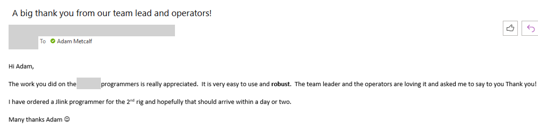
Despite these constraints, the replacement system was successfully developed and deployed into production within two days. In addition to restoring the original programming and test functionality, I simplified the operator workflow. The legacy application required the operator to interact with the user interface and interpret several intermediate results. In the replacement system, closing the fixture lid automatically initiated the complete programming and test sequence. The operator was presented with a clear Pass/Fail result when the cycle completed, with additional diagnostic information displayed only when a failure occurred. Operator feedback following deployment was very positive, and the simplified workflow reduced both interaction time and the opportunity for interpretation errors.
Operator Feedback (The email has been anonymised).
TODO. Images.
Areas
Bed of NailsProduction TestFirmware ProgrammingIndustrial AutomationLegacy System MigrationHardware IntegrationTelehealthcareAutomated Test Equipment
Specified National Instruments data acquisition and control systems to customer requirements, taking into consideration any need to interface with 3rd party hardware and software. This was a difficult operating environment due to the global chip shortages caused by the Covid 19 Pandemic, requiring a dynamic and flexible approach in order to meet customer specifications.
Recommending hardware to customers seeking replacements for obsolete systems.
My research involved designing and implementing a force-responsive low-level control scheme for an assistive robot aimed at aiding the rehabilitation of stroke patients.
I taught on the Design and Manufacture, Vibration and Control, and Computers in Engineering modules at the University of Leeds and at the overseas sister school at Southwest Jiaotong University in China.
I redesigned experiments for the Vibration and Control module to work with lower-cost hardware. Additionally, I developed new experiments for the Computers in Engineering module during the transition from expensive National Instruments (NI) hardware to more affordable Arduino hardware.
Employment
Engineering Intern
Mechanical Engineering Department, University of Leeds
June 2018 – Aug 2018
I rewrote and modernised module components for the Computers in Engineering Module taught to 1st year undergraduate students.
Employment
LabVIEW Developer - Part Time
Control Software Solutions Ltd
Aug 2017 – Feb 2018
Developing internal reuse code to accelerate project delivery. Successfully delivered a library to assist with unit testing in LabVIEW
Employment
Undergraduate Researcher
Mechanical Engineering Department, University of Leeds
Jul 2017 – Sep 2017
This is the second research project I completed as part of the Undergraduate Research and Leadership Scholarship.
The first part of my research involved developing a facial recognition login system for rehabilitation robotics. This built directly on my 2015 research, where I worked on a rehabilitation robotic system designed for stroke patients and children with cerebral palsy. A facial recognition login system was deemed the most appropriate option since these patients often have limited movement in their hands and arms. I successfully developed this system within approximately four weeks.
The second part of my research focused on enhancing the second-year Design and Manufacture module. I introduced a motion-tracking feature to one of the projects completed by Biomedical Engineering students. Previously, students were tasked with building a two-degree-of-freedom (2 DoF) robotic arm and programming it to follow a basic shape. I programmed a system that allowed a generic 2 DoF robot to track a student's arm movements using a computer vision tracking system. This motion-tracking addition simulates how a surgeon would manipulate a surgical robot, making the module more relevant to Biomedical Engineering.
Employment
Applications Engineer
National Instruments (NI)
Jun 2016 – Jun 2017
I worked directly with customers in the Northern European region to provide innovative solutions to engineering challenges. This role specifically involved delivering frontline support for the full suite of National Instruments software and hardware designed for control, test, and automation. During my time with National Instruments, I was also responsible for delivering professional-quality training in LabVIEW. Towards the end of my tenure, I earned the Certified LabVIEW Developer (CLD) qualification.
Selected Projects
Intern project: Laser Harp
Design and fabrication of a self-playing laser harp.
+
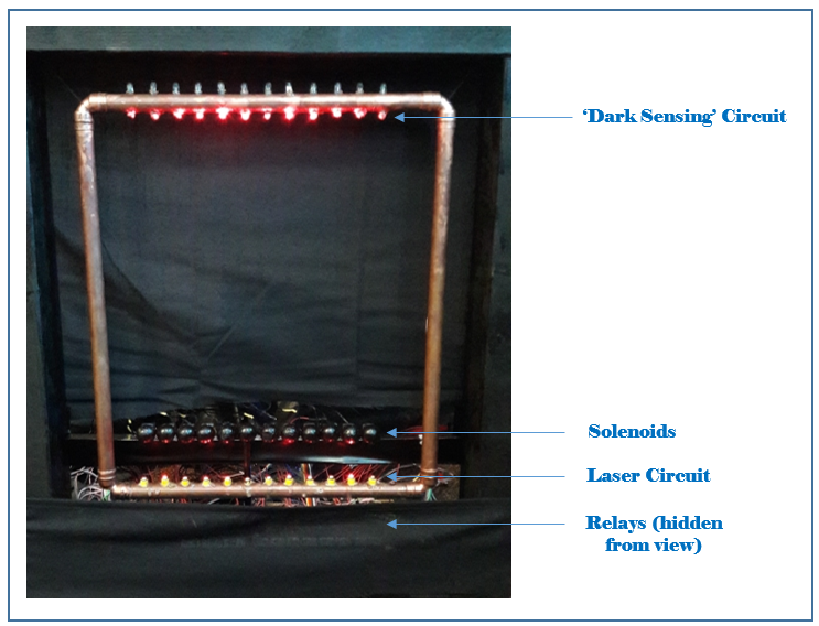
Created a self-playing laser harp using a combination of LDRs, laser diodes and a myRIO from National Instruments (NI). The project involved designing the optical detection system, programming the FPGA to interpret sensor data and control the actuators, and integrating all components into a functional musical instrument.
The completed laser harp prototype.
The laser harp can be played manually, or by presenting a USB flash drive containing MIDI files to the myRIO. The system parses the MIDI files and plays the music automatically.
Systems EngineeringAutomationElectronicsFPGALabVIEWmyRIO
Technologies
LabVIEW
Employment
Undergraduate Researcher
Mechanical Engineering Department, University of Leeds
Jul 2015 – Sep 2015
This research was completed as part of the Undergraduate Research and Leadership Scholarship.
My project involved designing, constructing, and programming a passive instrumented joystick for the rehabilitation of children with cerebral palsy and stroke patients. The device, termed the MyPAM Light, was intended to complement the rehabilitation process alongside an active instrumented joystick known as the MyPAM.
The MyPAM, which has already undergone medical trials, is designed for use during the initial six months of the rehabilitation process. However, its cost limits its installation to community facilities such as hospitals and schools. In contrast, the MyPAM Light was developed to be as economical as possible, making it suitable for installation in patients' homes. This accessibility allows patients to continue their rehabilitation independently, granting greater flexibility and potentially accelerating their recovery.
Education
BEng Mechanical Engineering - 1st Class (Hons)
Mechanical Engineering Department, University of Leeds
Sep 2014 – Jun 2018
Undergraduate Mechanical Engineering Degree, achieved a high 1st Class classification. I was placed on both the 2014/15 and the 2015/16 Engineering Dean's list for academic achievement.
In the first year of my degree I successfully applied for the very competitive Undergraduate Research and Leadership Scholarship. The scholarship ran for 2 years and consisted of leadership training and 2 summer internships performing research. The research was in the area of medical robotics.
After my time with the Undergraduate Research and Leadership Scholarship I was awarded the Edward Boyle prize by the Royal Society of Arts↗.
Employment
Home Delivery Driver
ASDA
Sep 2013 – Oct 2014
My responsibilities included ensuring the timely delivery of groceries to customers. I delivered according to a tight schedule, but despite this I delivered in a manner which was safe and considerate to all road users. I ensured a high quality of customer service.
This job allowed me to remain financially stable whilst I was studying for my Access Diploma at Leeds City College.
Education
Access Science: Engineering (Distinction)
Leeds City College
Sep 2013 – Jun 2014
The Access Science: Engineering course provided me with a solid foundation in mathematics, physics, and engineering principles. I achieved 60 credits at Distinction in the course, which enabled me to progress to higher education in Mechanical Engineering.
Employment
Heavy Goods Vehicle Mechanic - Temporary Contract
Rhondda Cynon Taff Council
Apr 2013 – Jun 2014
I was responsible for maintaining the council fleet of vehicles, which included Iveco Daily vans, Eagle Elite 2 refuse lorries, Scarab road sweepers, MAN gritters, MAN tippers, and the full range of highways vehicles.
My role involved conducting annual vehicle inspections, diagnosing and repairing faults, and performing pre-MOT inspections. Tasks ranged from routine maintenance, such as changing oil filters in transit vans, to diagnosing and repairing complex hydraulic systems in modern refuse lorries.
Employment
Vehicle Mechanic
British Army
Mar 2008 – May 2013
I have operated, maintained, inspected, and diagnosed faults on vehicle fleets in Northern Germany and Afghanistan as a Class 2 Vehicle Mechanic. The vehicles I have worked on include Land Rover, Bulldog, CVRT, Warrior, Wolfhound, CRARRV, MAN trucks, Warthog, Bedford, DAF, Mastiff, Ridgeback, Jackal, Coyote, and SVR. My responsibilities ranged from performing basic services, such as filter changes, to handling complex tasks like engine replacements and complete vehicle overhauls.
Towards the end of my career in the British Army, I was responsible for company-level fleet management. This role involved ensuring that inspection schedules were consistently adhered to for the fleet of approximately 60 vehicles assigned to 22 Field Company (2nd Bn REME). Additionally, I oversaw the ordering of spare parts and the coordination of necessary repairs. To maintain high operational standards, I regularly participated in conferences with senior battalion-level fleet management.